Español
 Русский
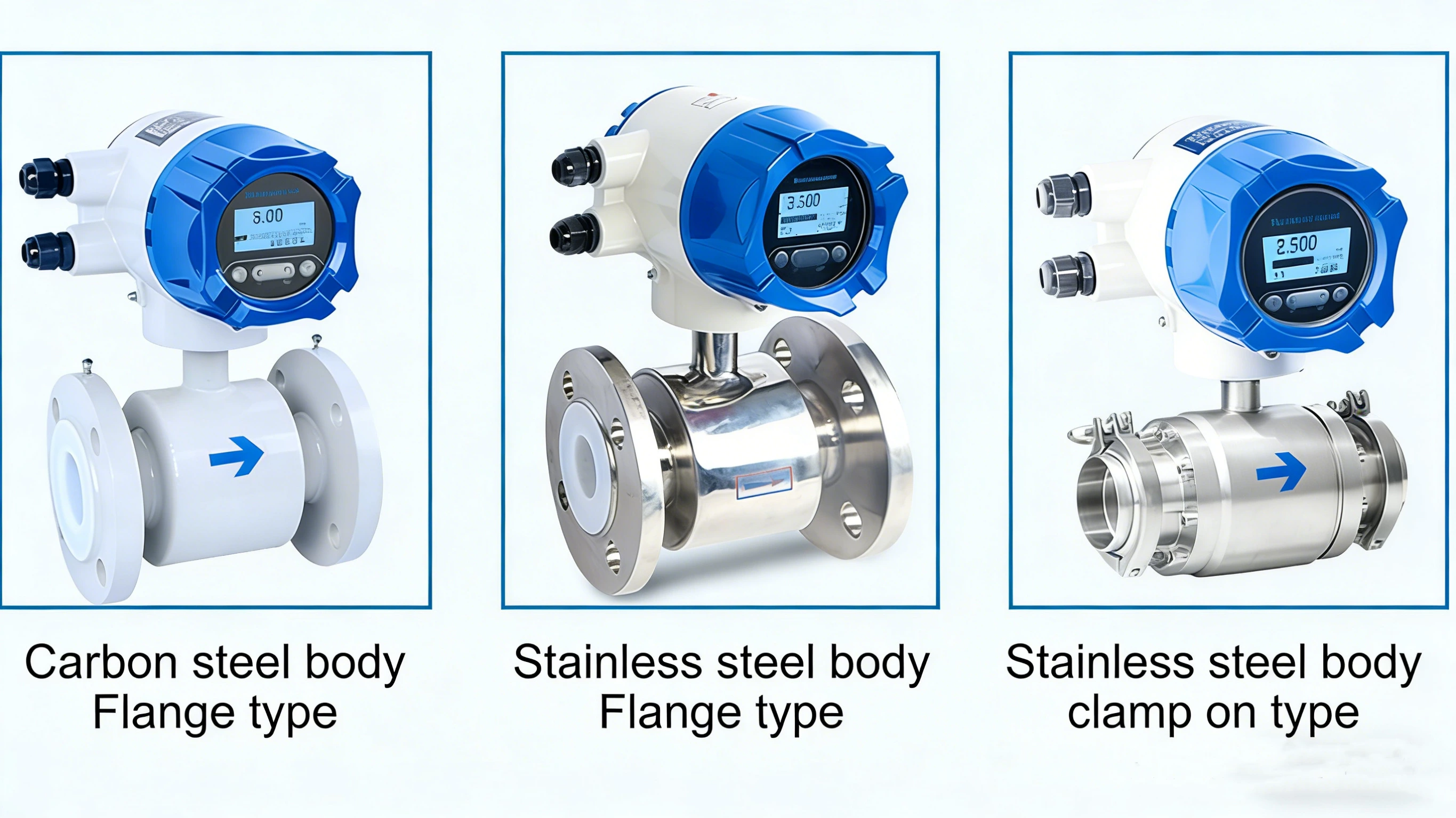
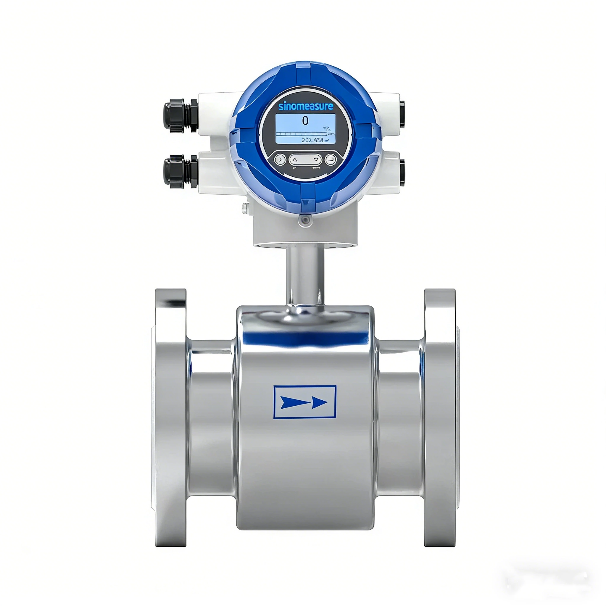
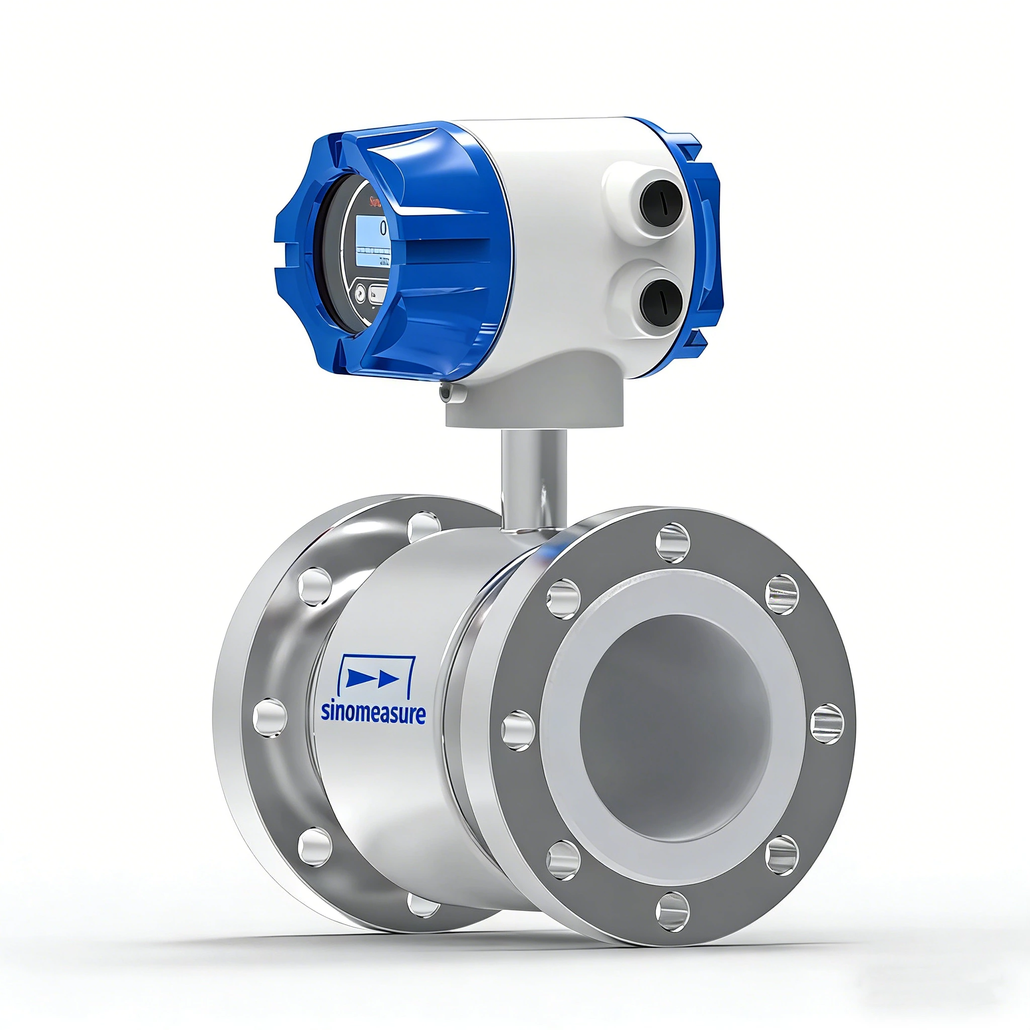
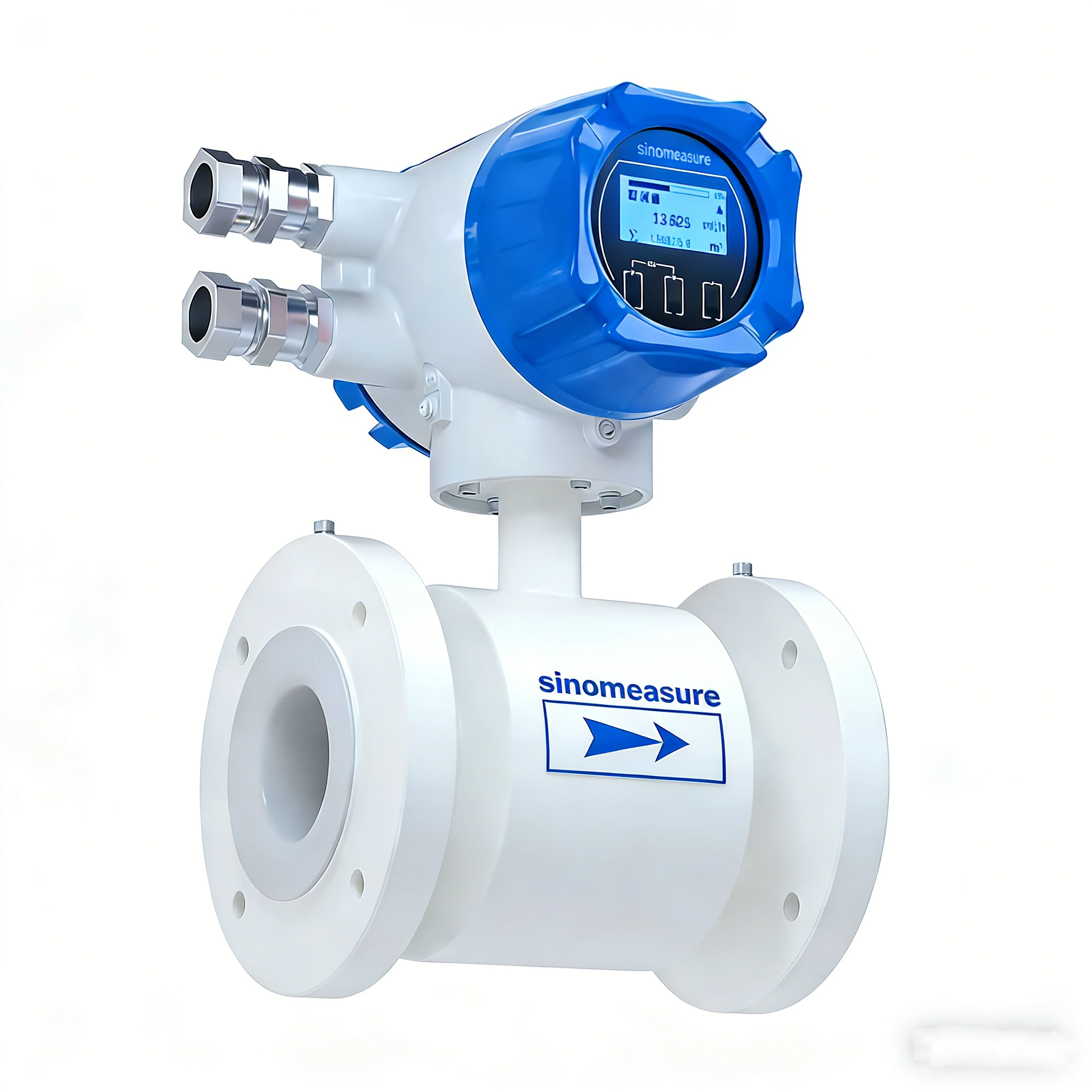
 SIN-LDG-A100 Electromagnetic flow meter
The electromagnetic flowmeter is designed based on the Faraday electromagnetic induction principle and is used to directly measure the flow rate of conductive liquids in closed pipelines. During on-site monitoring and display, standard current signals, pulse signals, and RS485 digital signals can be output for recording, adjustment, and control, achieving automatic detection and control. It can be widely used in industries such as tap water, chemical industry, coal, environmental protection, light textile, metallurgy, papermaking, etc.
-
Pipe diameter: DN10~DN1000
-
Accuracy: ±0.5% of measured value; ±0.3% of measured value (available for selected pipe sizes)
-
Repetitiveness: 0.16%
-
Electric conductivity: ≥50μS/cm


-
Specification
| Measured variable | Direct measured: Flow velocity Calculated value: Volume flow, mass flow. |
|
| Flow velocity range | Typically range of flow velocity: 0.5m/s~5m/s | |
| Nominal diameter | DN10~DN1000 | |
| Communications | RS485; MODBUS-RTU; Hart communication (optional) | |
| Relay (Remote type optional ) | 2 channels SPST; 250VAC; 3A | |
| Supply voltage | 100VAC~240VAC, 50/60Hz; 20VDC~28VDC | |
| Power consumption | ≤15W | |
| Reference operating conditions | Medium: water Temperature: 20℃ Pressure: 0.1MPa Installation requirements: Inlet run≥10DN, Outlet run≥5DN | |
| Accuracy | ±0.5% of measured value; ±0.3% of measured value (available for selected pipe sizes) Note: Applicable to flow velocity range of 0.5 m/s to 5 m/s | |
| Repetitiveness | 0.16% | |
| Medium temperature range | CR liner: -10℃~70℃ PU liner: -10℃~60℃ PTFE/F46 liner-10℃~120℃ | |
| Rated pressure (Customizable for high-pressure applications) | DN10~DN250: PN<1.6MPa DN300~DN1000: PN<1.0MPa Note: For certain specifications, actual values may vary; refer to the nameplate for exact information. High-pressure versions are available upon request. | |
| Conductivity | ≥50μS/cm | |
| Ambient temperature | Integrated type | -10℃~55℃ |
| Remote type | Converter:-20℃~55℃ Sensor: -10℃~55℃ | |
| Storage temperature | -20℃~55℃ | |
| Protection level | Integrated type | Standard: IP65 |
| High protection: IP66/IP67 | ||
| Remote type | Sensor: IP65 Converter: IP68 | |
-
Measuring principle
The operating principle of the electromagnetic flowmeter is based on Faraday's law of electromagnetic induction. The two electromagnetic coils at the upper and lower ends, as shown in Figure 1, generate a constant or alternating magnetic field. When the conductive medium flows through the electromagnetic flowmeter, the induced electromotive force can be detected between the left and right electrodes on the wall of the flowmeter tube. The magnitude of the induced electromotive force is proportional to the electrically conductive medium flow rate, the magnetic induction density of the magnetic field, and the width of the conductor (the inner diameter of the flowmeter measuring tube), and the flow rate of the medium can be obtained by calculation. The induced electromotive force equation is as follows:
E=K×B×V×D
Where: E-Induced electromotive force
K-Meter constant
B-Magnetic induction density
V-Average flow speed in the cross-section of the measuring tube
D-Inner diameter of measuring tube
When measuring the flow, the fluid flows through a magnetic field which is perpendicular to the flow direction. The flow of conductive fluid induces a potential proportional to the average flow velocity, thus requiring the conductivity of the measured flowing liquid to be higher than the minimum conductivity. The induced voltage signal is detected by two electrodes and transmitted to the converter via a cable. After a series of analog and digital signal processing, the accumulated flow and real-time flow are displayed on the display of the converter.
-
Magnetic flow meter installation
Here are some general guidelines for installing a magnetic flow meter:
Pipe diameter: Select a flow meter that is appropriate for the pipe diameter. The flow meter should fit the size of the pipe and should be installed at the correct orientation.
Straight pipe runs: The flow meter should be installed in a section of pipe that has a straight run of at least 5 pipe diameters upstream of the meter and 2 pipe diameters downstream of the meter.
Positioning: Install the flow meter in a horizontal pipe, with the flow going from the larger diameter section to the smaller diameter section. If installed vertically, the flow must be upward.
Inlet and outlet conditions: Ensure that the inlet and outlet piping are straight, with no obstructions or bends in the piping near the meter. The flow should be fully developed, without any swirl or turbulence, and the pipe should be level to prevent air pockets from forming.
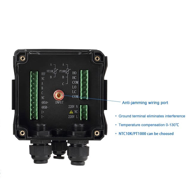
Grounding: Magnetic flow meters require grounding to eliminate electrical noise and ensure accurate readings. Proper grounding is essential for the operation of the meter.
Electrical connections: Connect the electrical leads to the appropriate terminals and ensure that the wiring is correct.
Material compatibility: The materials used for the flow meter and the piping should be compatible with the fluid being measured.
Calibration: Magnetic flow meters require calibration to ensure accurate measurements. Calibration should be performed according to the manufacturer's recommendations and should be repeated periodically.
It is important to consult with the manufacturer's specific installation guidelines and work with an experienced engineer to ensure proper installation and accurate measurement of fluid flow.
-
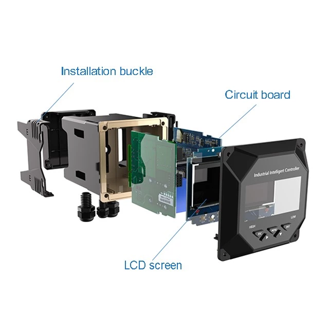
Description